


Dummy Load
0102030405
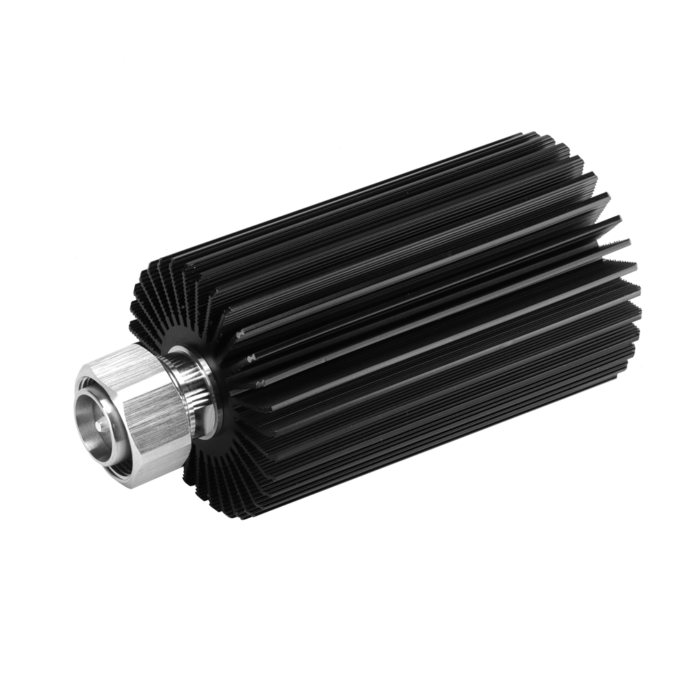
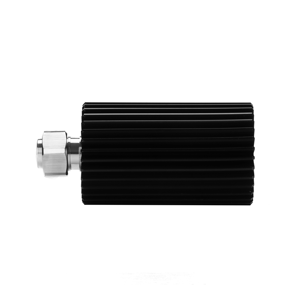
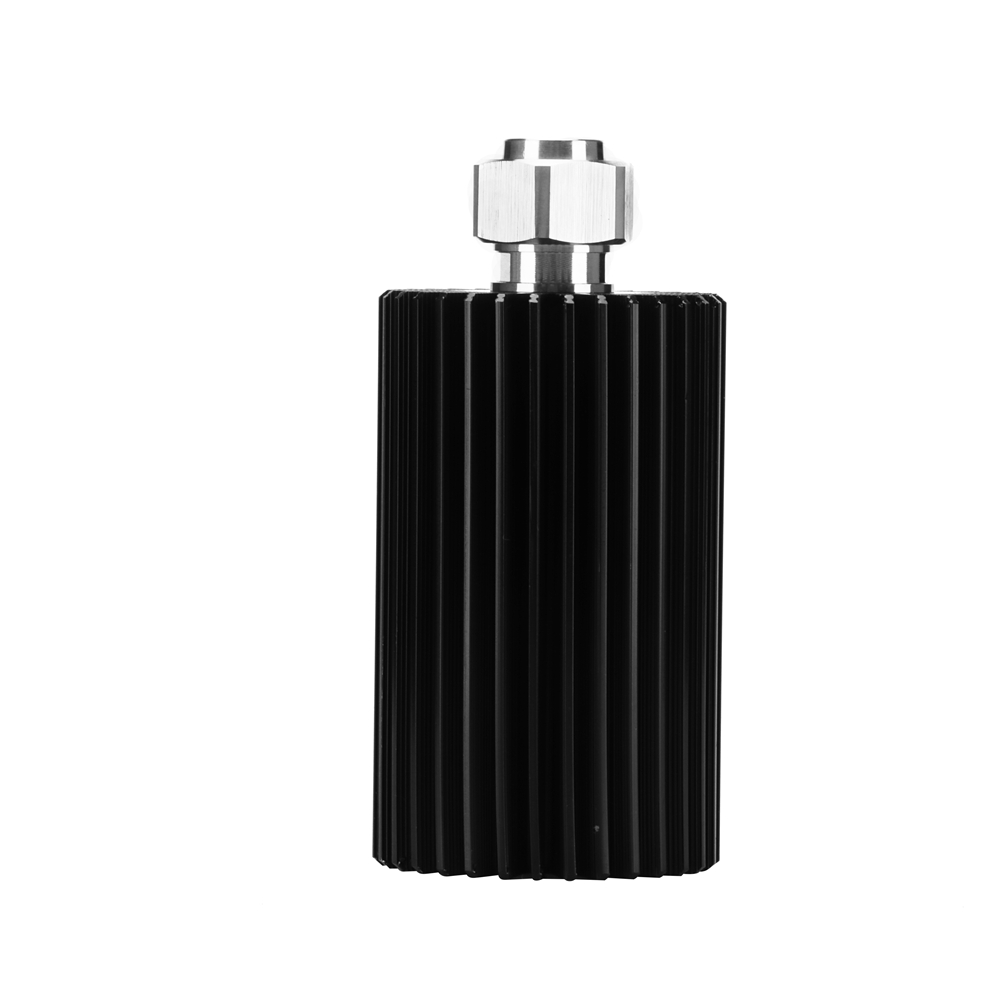
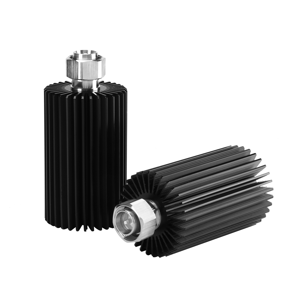
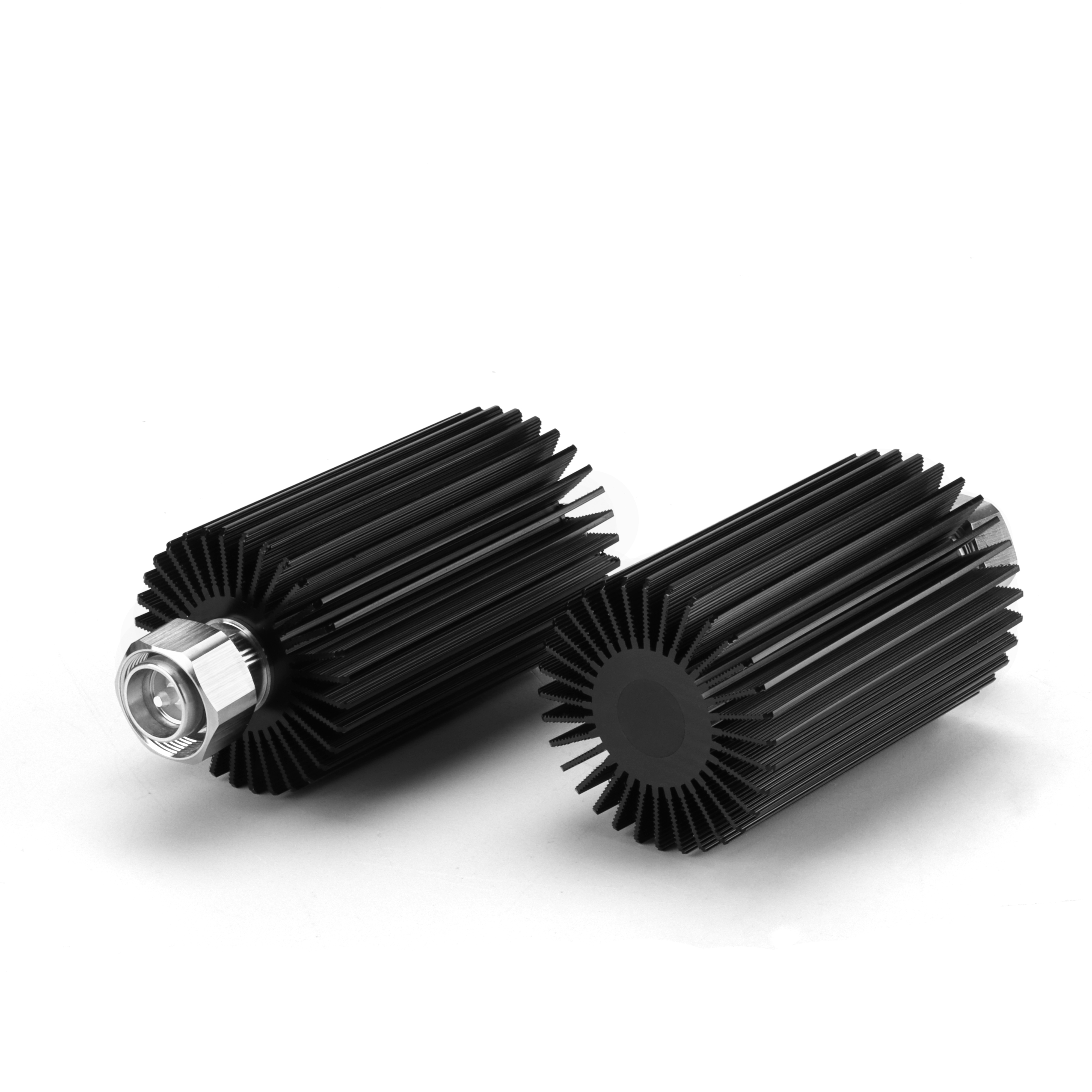
RF 50 Ohm 50w N Female Connector Termination Dummy Load
Specification
| Electrical Specifications: | ||||||
| Power | 2W | 5W | 25W | 50W | 100W | 200W |
| Frequency Range | DC-3GHz | |||||
| Impedance(Ω) | 50 | |||||
| VSWR | ≤1.2:1 | |||||
| PIM3(dBc) | ≤-120@2X33dBm | ≤-105@2X43dBm | ||||
| PIM5(dBc) | ≤-145@2X33dBm | ≤-120@2X43dBm | ||||
| Connectors Type | N-Male,N-Female,DIN-Male,DIN-Female | |||||
| Operating Temp.(℃) | -20~+55 | |||||
| Humidity | ≤95% | |||||
| Dimension(mm) | Φ16X30 | Φ16X30 | Φ50X68 | Φ50X105 | 146X100X60 | 226X142X64 |
Low PIM Dummy Load-DC-3GHz 50/100/200W N,DIN type
| Electrical Specifications: | |||
| Power | 50W | 100W | 200W |
| Frequency Range | DC-3GHz | ||
| Impedance(Ω) | 50 | ||
| VSWR | ≤1.25:1 | ||
| PIM3(dBc) | ≤-150@2X43dBm | ||
| PIM5(dBc) | ≤-160@2X43dBm | ||
| Connectors Type | N-Male,N-Female,DIN-Male,DIN-Female | ||
| Operating Temp.(℃) | -20~+55 | ||
| Humidity | ≤95% | ||
| Dimension(mm) | 185X142X54 | 185X142X54 | 185X142X80 |
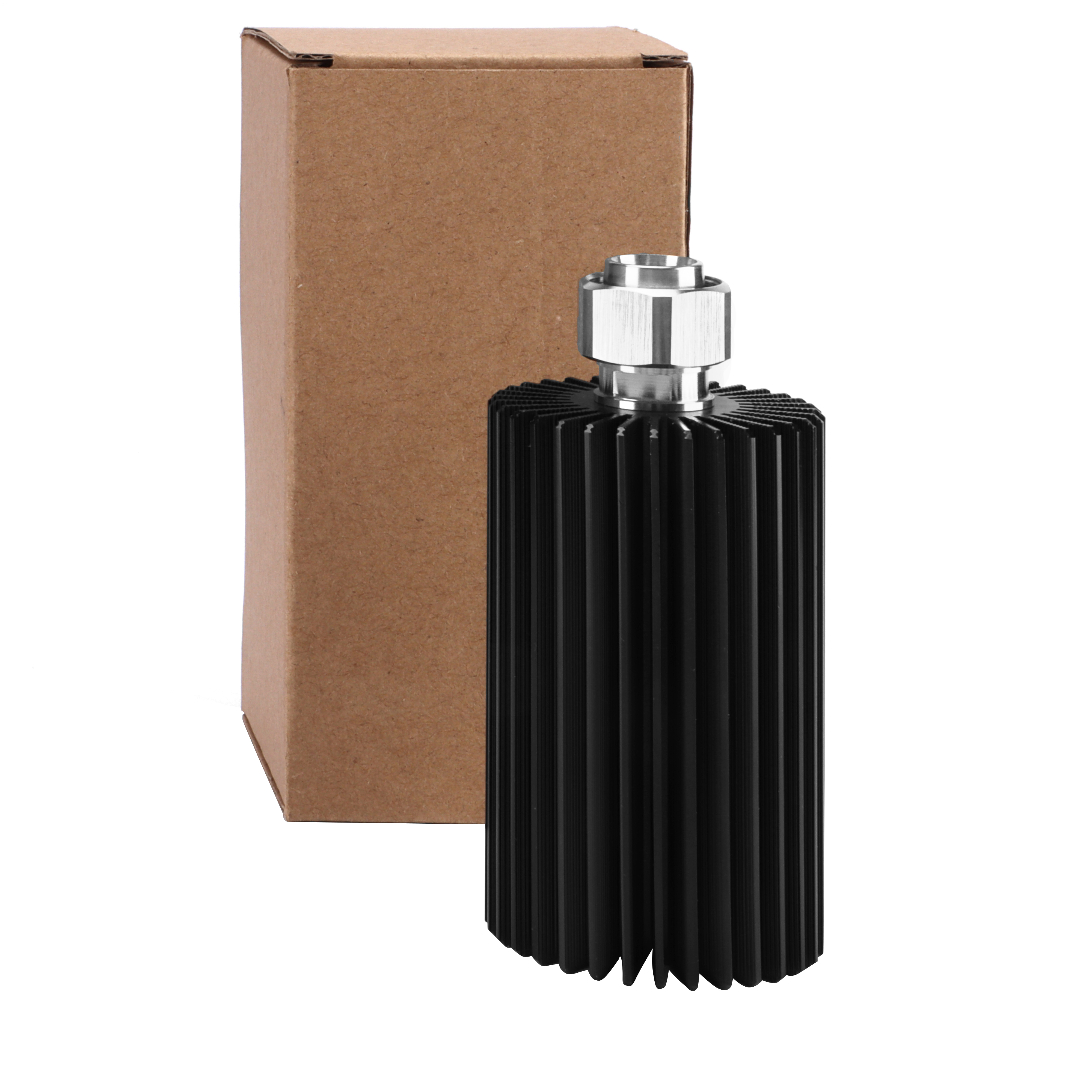
DETAILS
The Dummy Load is in a way so that it has a similar impedance to the real device that will be connected to the RF System.Not using a dummy load and leaving the port open, can result in some unwanted reflections which can damage the RF System.
The Dummy Load is in a way so that it has a similar impedance to the real device that will be connected to the RF System.Not using a dummy load and leaving the port open, can result in some unwanted reflections which can damage the RF System.
Also, using a real antenna in the testing phase can result in some unwanted transmission in the lab which will interfere with other devices and technologies being tested.
WARNING
When the input power is high than dummy provide, this is damage the dummy load.