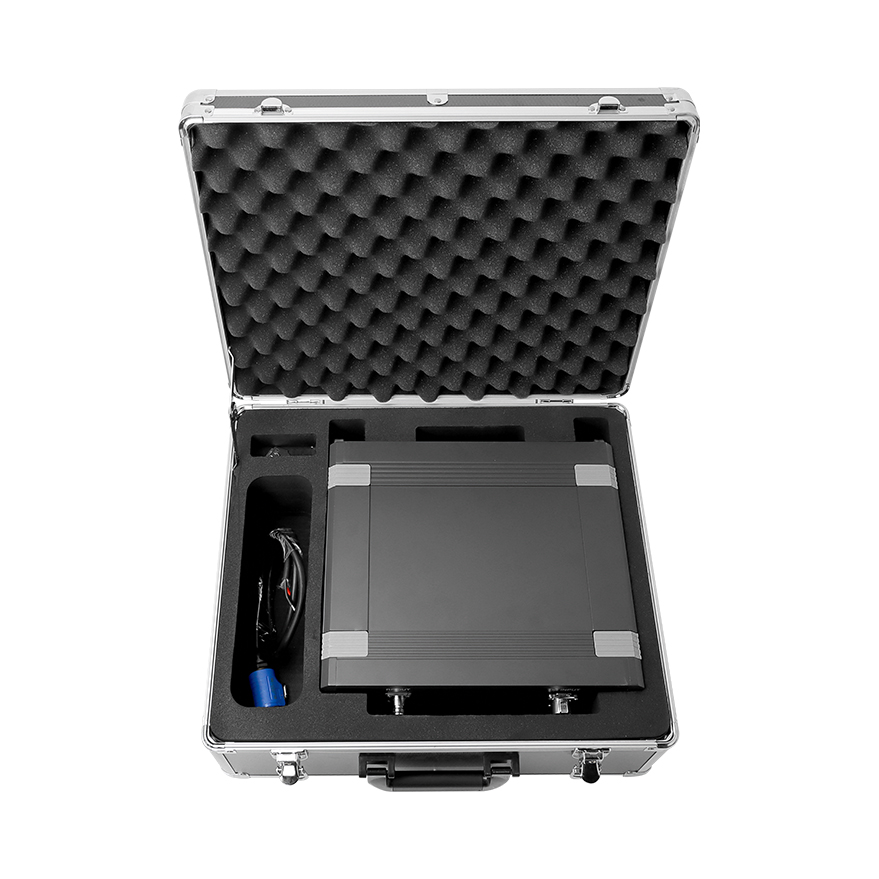


Signal Jammer
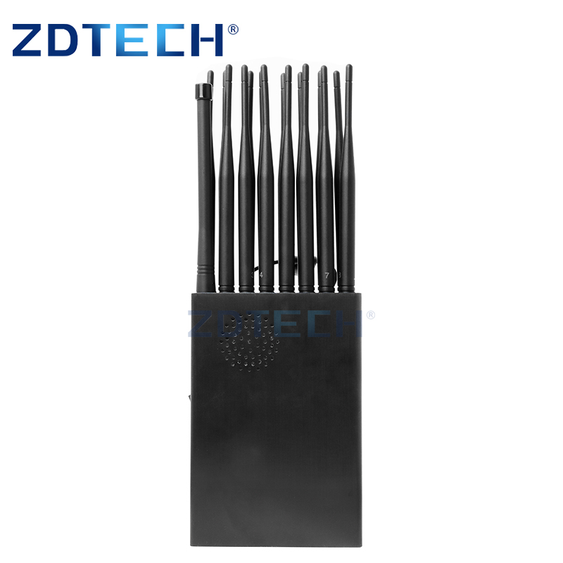
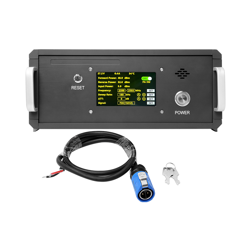
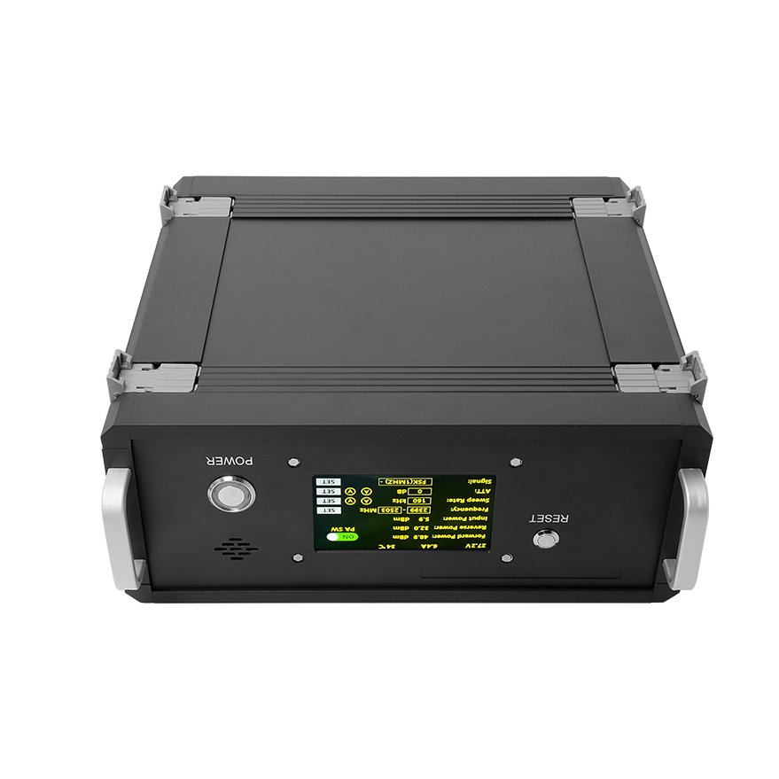
100W DDS ALC RACK version with touch screen for Military Prison FPV UAV Jammer
PRECAUTIONS
Item |
Parameter |
Remark |
|||
working frequency |
600M-1000M |
|
|||
power |
100W |
|
|||
Operating Voltage |
28V |
24-36V |
|||
Conyersion efficiency |
≥42% |
@100W |
|||
Adjustable output power |
10W~100W |
Software set power |
|||
ALC power adjustment range |
≥20dB |
Voltage Controlled Attenuation |
|||
gain |
50±1.0dB |
|
|||
In-band fluctuation |
≤2.5dB |
peak |
|||
spurious emissions |
In working band |
≤-15dBm/1MHz |
Measured when the center frequency plus CW signal to the maximum output power |
||
|
Out-of-band |
9KHz~1GHz |
No higher than normal noise loor clutter |
|
|
|
|
1G~12.75GHz |
|
|
|
Maximum allowable input power |
2+10dBm |
Lasts 1min without damage |
|||
Input VSWR |
≤1.35 |
Add+28V,standard network output-10dBm |
|||
Output VSWR |
≤1.35 |
No power,standard network output -10dBm |
|||
|
≤1.35 |
Power On,Dual Directional Coupler Test |
|||
High and low temperature test |
Working environment temperature (℃) |
-10~+65℃ |
Low temperature can start,monitoring works normally |
||
|
Gain Stability |
±1.5dB@-40°℃~+65℃ |
|
||
|
power stability |
±1dB( -40°C~+65°℃ |
|
||
Power Requirements |
≥8.5A @+28Vdc; |
CW output 100W |
|||
Power supply interface,communication interface RS485 |
7W2 |
Male,1:485A;2:485B |
|||
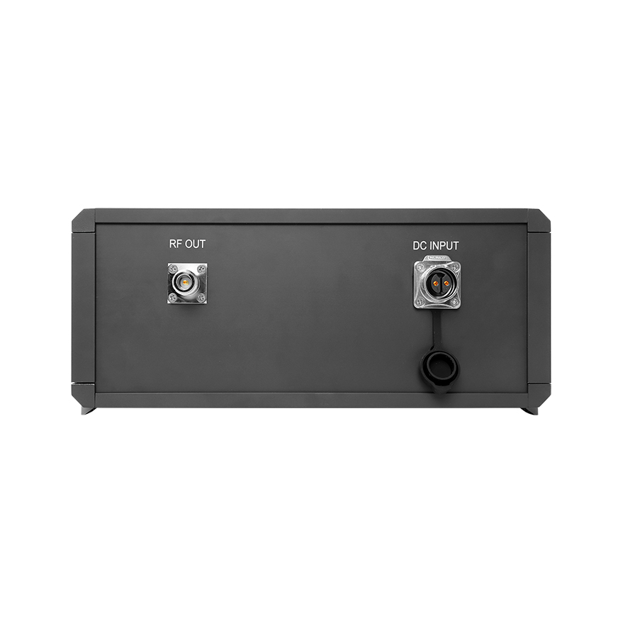
RF output connector |
N-Female connector |
||||
with 3 LED lights |
POWER:Power indication;RUN:Running indication;ALARM:Alarm indication |
||||
physical dimension |
|
||||
weight |
|
||||
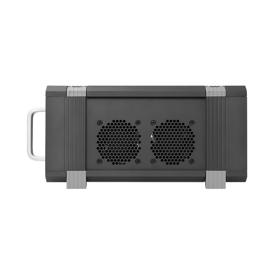
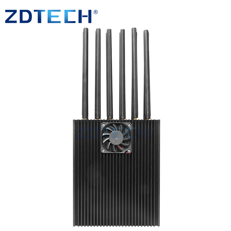
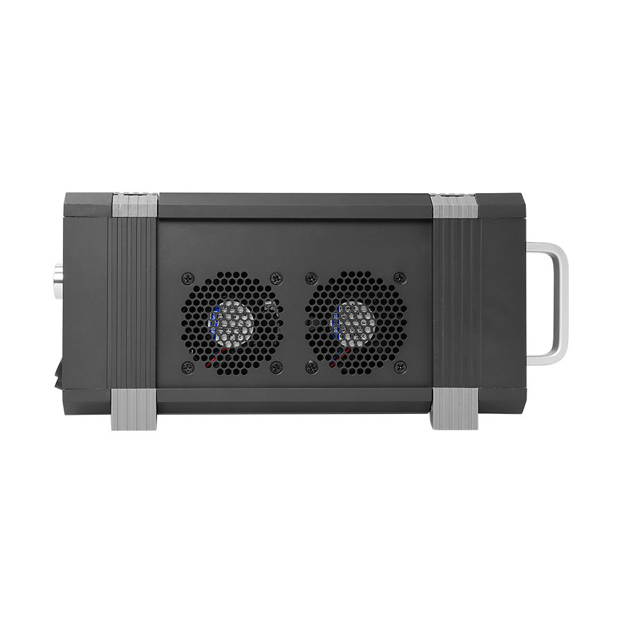
Appearance (how to use) |
Signal source power amplifier integrated module (fixed on the radiator) |
||||
Monitoring Function |
Description |
Remark |
|
|
Amplifier part setting parameters |
Amplifier switch |
Turn the amplifier on or off |
|
|
Alarm switch |
Enable and disable the alarm function |
|
|
Downlink Power Control |
The maximum output power of the power amplifier can be se, the adjustment range is ≥20dB,and the high,medium and low power levels can be set |
|
|
Amplifier over temperafure alarm |
The high temperature power amplifier shutdown threshold can be set,the power amplifier temperature exceeds 85 degrees,it will automatically shut down;65 degrees will automatically restore |
|
|
Amplifier over power alarm |
The actual power value is 2dB higher than the downlink ALC start control threshold and close |
|
|
Power amplifier standing wave alarm |
When the standing wave detection of the power amplifier is greater than 4,the power amplifier is automatically turned off |
|
|
Amplifier overcurrent alarm |
When the deteclion current of the power amplifier exceeds 12A the power amplifier is automatically tumed off |
|
|
Amplifier under-power alarm |
When the power amplifier detection power is less than 33dBm an under-power alarm is displayed |
|
|
Amplifier overvoltag alarm |
When the power amplifier voltage exceeds 32V,the power amplifier will automatically shut down |
|
|
Amplifier undervoltage alarm |
Amplifier voltage<20V displays under-voltage alarm |
|
|
Amplifier part query parameters |
Amplifier switch status |
If the power amplifier is set to"OFF",the query should be the state of power amplifier off state;otherwise,it is the open power amplifier state |
|
|
Downstream output power level value |
Detect power amplifier output power value,detection range Pomax+2,Pomax-20) |
Detection accuracy:Pout±1dB |
|
Downward standing wave ratio |
The standing wave is nomally 1.2,when the load is mismatched he query value is 4.0 |
|
|
temperature query |
Detect the internal temperature of the module,detection range -40℃~+100℃ |
Detection error.±3P℃ |
|
ALC value query |
The displayed value is equal to the actual set ALC value |
|
|
Voltage detection |
Detection module working voltage |
|
|
Current Detection |
Detection module operating current |
|
|
Signal generator settings |
Frequency setting mode 1 |
Any single freuency point setting within the range |
The frequency setting accuracy is 1M,the maximum frequency bandwidth is 500M,and the maximum is 6G |
|
Freguency setting mode 2 |
Set the broadband frequency sweep mode,parameters such as frequency,interval,and step can be set |
|
|
Freguency settin mode 3 |
Set any 4 sub-frequency segments within the bandwidth,and the sub-segments are incremented |
|
Module Communication Protocol |
|
RS485 |
|
Interface definition |
|
+:28V,-:GND;1:485A.2:485B |
|